|
| |
Solid Core Motorized XY Table
|
|
Home
>
Motorized XY Stages
|
|
|
|
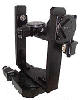
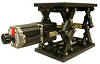
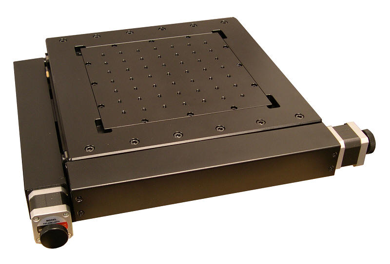
The AU200-100X100-SC Solid Core Motorized XY Stage is a high resolution, low profile, high load capacity, horizontal stage that can be easily integrated into any current or future application.
The linear travel of the X and Y axes is 100mm x 100mm (3.937 in. x 3.937 in.) and the resolution of the X and Y axes is 20
microns
(non-micro-step) or 1 micron
(20 micro-steps per step motor driver in use), the typical repeatability is 2
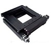
microns, and the typical positional accuracy is 3 microns. A low profile XY stage measuring just 80 mm (3.150 in.) high with a compact footprint (including the motors) of 348 mm x 348 mm (13.701 in. x 13.701 in.), the stage is
designed for
: Alignment, assembly, laser drilling and machining, industrial, medical, testing, scanning, semiconductor handling, and optical applications.
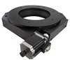
Preloaded V-groove and crossed roller bearings and ground 4 mm per-turn lead screws having just 2 microns of backlash, all contribute to the high precision and stiffness of the AU200-100x100-SC Stage. The table of XY stage measures 300 mm x 300 mm (11.811 in x 11.811 in.) and has a precision pattern of 21 drilled and threaded mounting holes to easily add special tooling or fixtures, and for easy integration into new and existing applications. Additional tooling plates are also available for custom and interchangeable applications.
The standard two-phase (1.8o) stepper motors have knobs for manual adjustments of each axis of the stage, however, the knobs can be replaced with incremental encoders for position verification.
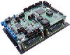
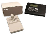
This stage requires a
Motion Controller
that can be ordered as a complete plug-and-play system with RS-232, USB, joystick and keypad control.
|
|
Specifications
|
Type
|
AU200-100x100-SC
|
|
Structure Description
|
Range of Travel
|
100 mm
|
|
Table Size
|
300 mm x 300 mm
|
|
Actuator Type
|
Lead Screw (4 mm per turn, optional 1 mm per turn)
|
|
Travel Guide
|
Precision V-groove & Crossed Roller
|
| |
|
|
Base Material
|
Aluminum Alloy
|
|
Surface Treatment
|
Black Anodized
|
|
Load Capacity
|
50 kg
|
|
Weight
|
14.5 kg
|
|
Typical Accuracy Description
|
Resolution
|
20 microns (Full Step)
1 microns (20 Micro-steps per Step Motor Driver in use) |
|
Repeatability
|
2 microns
|
|
Positional Accuracy
|
10 microns
|
|
Electrical
Description
|
Motor |
|
Two Phase Stepper Motor (1.8 Deg)
|
|
| Typical Phase Resistance |
3.8 Ohms, Bi-directional |
| Typical Phase Current |
1 Amp |
| |
|
Pin Assignment and Description
|
|
1
|
+5 VDC
|
|
2
|
CCW Limit Switch
, Open Collector, Normally Open, Needs Pull up Resistor
|
|
3
|
CW Limit Switch, Open Collector
, Normally Open, Needs Pull up Resistor
|
|
4
|
Common
|
|
5
|
Not Connected
|
|
6
|
Stepper Motor Phase A+ |
| 7 |
Stepper Motor Phase A- |
| 8 |
Stepper Motor Phase B+ |
| 9 |
Stepper Motor Phase B- |
|
| |
|
DB-9 Male Connector
|
| |
| |
| |
| |
| |
| |
| |
|
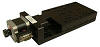
Accessories Description
|
Servo Motor
Optical Encoder
|
|
|
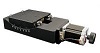
Stepper Motor Driven Mechanical Drawing

|
|
|
Ordering Information
|
Part No.
|
Description
|
Amount
|
|
AU200-100x100-SC-01
|
Stepper Motor Driven
Linear
Solid Core
Two-axis Stage,
Range of Travel: 100 mm x100 mm
|
Click to Get a Quote
|
|
AU200-100x100-SC-02
|
Three Phase Brushless Servo Motor with Quadrature Incremental
Optical Encoder Driven
Linear
Solid Core
Two-axis Stage,
Range of Travel: 100 mm x100 mm
|
Click to Get a Quote
|
|
AU200-100x100-SC-03
|
DC
Servo Motor with Quadrature Incremental
Optical Encoder Driven
Linear
Solid Core
Two-axis Stage,
Range of Travel: 100 mm x100 mm
|
Click to Get a Quote
|
|
AU200-100x100-SC-04
|
Stepper Motor Driven
Linear
Solid Core
Two-axis Stage
with 500 Cycles per Revolution Quadrature Optical Encoder
Mounted at the back of the Stepper Motor
,
Range of Travel: 100 mm x100 mm
|
Click to Get a Quote
|
|
Related Products
|